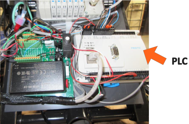
1. Location of the PLC
You can use the height pedal to lower the table so that you can see these components through the gap in the skirting at the foot end of the table. You can get easier access to the components by removing the screw that holds the plastic to the top frame as you face the foot end and also the screw that holds the inner section to the base at the foot end.
2. Power to the PLC
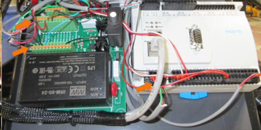
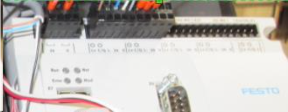
The red and black wires to the first terminals of the small green circuit board (indicated by the two orange arrows in the top left of the image below) supply power to the connector in the lower left corner of the LC (see third orange arrow in the lower center of the image below)
3. Power Connection on the PLC
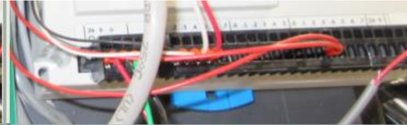
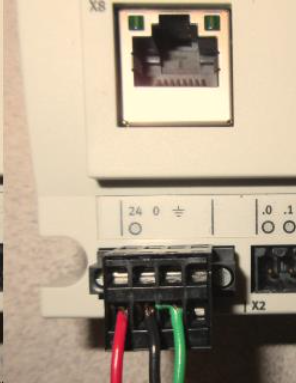
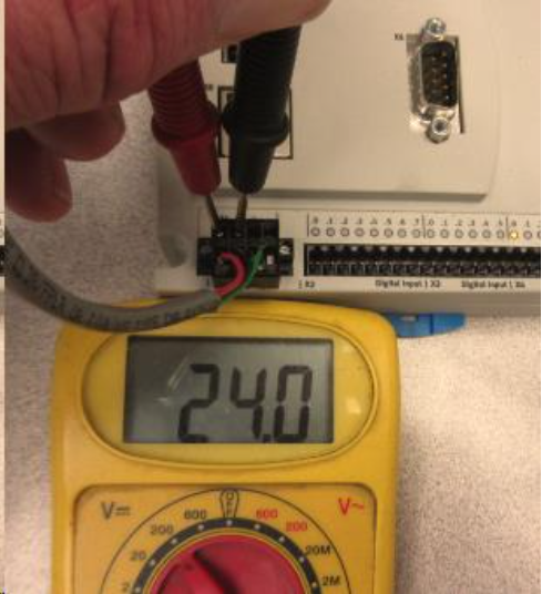
When power (24 volts DC) is received at the PLC the circle below the "24" will be green and several of the LED's will be illuminated along the top of the PLC. A meter can be used to see if 24 volts is being received to the connector. Touch one probe to the metal area above the red wire and the other probe on the metal above the black wire. The metal is very visible in the first photo below.
4. Verify Connections
If the touchscreen powers up but there is no voltage to the connector at the PLC per Step 3, then you can verify that the wires are secure at the PLC and also that the same red and black wires are secure at the first terminals of the small green circuit board. Unplug the table when disconnecting and connecting.
At PLC: Use a very small flat blade screwdriver to insert in the metal area of the connector as far away from the wire as you can and then tilt the handle away from the wires to release.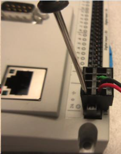
At circuit board: Use the same small flat blade screwdriver to push down the orange tab next to the wire to release it.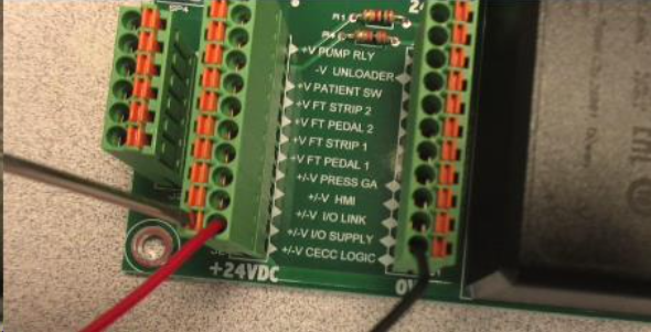
5. Replace the PLC
If there is power to the PLC yet there are no LED's then the PLC needs to be replaced. Make sure the table is unplugged while disconnecting and connecting wires.
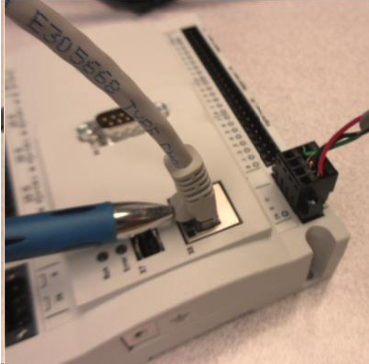
Each black connector can be grasped and pulled straight up from the board and inserted at the same location of the new PLC. One exception is the power connector that you focused on for Step 3, which is secured by a small screw on each side. You can use the same flat blade screwdriver as earlier to loosen the screws and pull it up.
The communication cable is disconnected by hand similarly as you would a phone cable, by pressing the tab with your thumb (indicated by the pen in the photo below).
The PLC is released from a din rail on the plastic mount board by inserting a screwdriver in the blue tab at the bottom edge of the PLC and sliding the blue tab down and away from the PLC. You should be able to lift the PLC straight up.