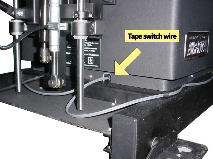
Access will need to be made at the head end of the base to insert the switch wires. See below:
Parts:
- HB144 - tape switches (qty 2) with female connectors
- H9679 - 35" of 2-lead wire, brown and blue (qty 2)
- H61 - 6" wire tie - (qty 10)
- H7834 - 5/16" cable damp (qty 2)
- H482 - #6x7/16 self-tap pan hd (qty 2)
- H3697 - strain relief
Prep Item #2 (H9679): Strip 12" of outer cover and crimp a ferrel on the blue wire only. Crimp a male connector on the brown and blue at end connecting to tape switches.
Location of Entry:
The metal strip behind the plastic skirt has two holes at the head end usually used by the power cord and the corded pedal for height. If your table has a corded pedal then you will need to drill a 19/32" mount hole in the metal strip just to the right of center as if looking from outside the table.
Notch the skirt:
- Note that the size of the notch in the skirt where the power cord exits the base is approximately 3/4 x 3/4"
- Remove the screws holding the inside skirt to the base and locate the other hole in the same metal base strip as the power cord
- Mark the skirt with a pencil for a notch at the second location similar to the notch for the power cord
- use diagonal cutters or a hacksaw to cut from the bottom edge along the two lines
TIP: After you make the parallel cuts, use a utility knife to score the top of the tab and then bend it back and forth with pliers until it breaks off.
View from inside base:
The tape switch wires entire the base and connect to a cord that will route up the scissor. Both 35" cord runs up the scissor with the other cables.
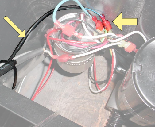
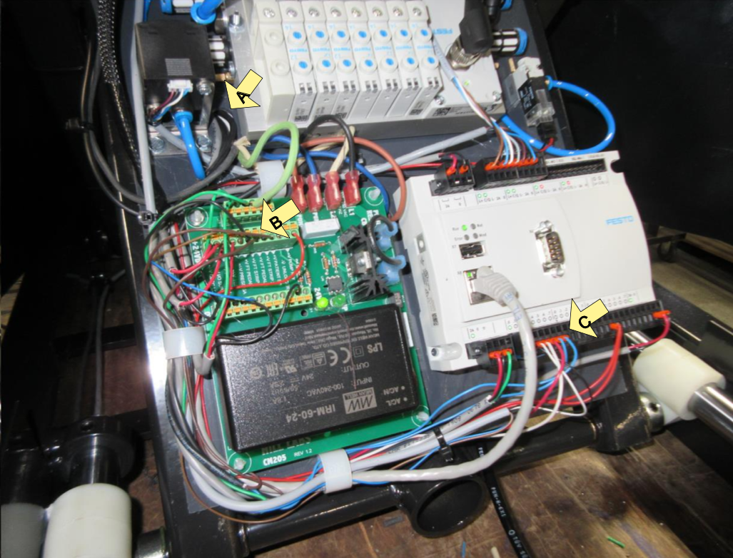
The cord from the foot switch follows another cord up the scissor and passes through the hole in the board from the back side at location A in the photo below. The cord will follow the left edge of the board. The brown wire of one tape switch will connect to the green Power Supply circuit board at the terminal identified by "+V FT PEDAL 1". The brown from the other switch will connect to "+V FT PEDAL 2". This is shown at location B in the photo below.
The blue wires of the switches will route around the lower left corner of the board with other cords as shown in the photo. They will connect to the white PLC in the right corner of the board, connecting at terminals 4 and 5 of the Digital Input section as show at location C below.
Refer back to the first picture to secure the switch wire where it enters the base. The Heyco cord restraint clamps around the wire at the point it enters the hole. The restraint is squeezed with pliers and pushed into the hole of the steel strip. It is a tight fit.
A plastic cable clamp was provided if you want to add it to the top of the base to direct the wire toward either side of the table. This is recommended if the table has a raised head to prevent the cord from getting pinched by the bottom of the chrome rods.