TO ACCESS:
Remove the six screws that secure the outer plastic enclosure to the top frame. The enclosure can be lowered to rest on the base after the pelvic tension knob is unthreaded and removed.
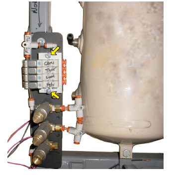
VALVE LOCATIONS:
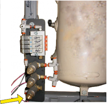
The photo shows the location of the manifold and stand alone valves just above the air compressor and to the side of the air tank. The arrow indicates the unloader valve. It is the one with the unplugged hole in the top. The brass colored valve above it is the Air Out valve for the thoracic breakaway. The top brass valve is the Air In valve.
These two valves control pressure in the breakaway cylinder when the Breakaway button is lit on the control box.
TO DISCONNECT WHEN REPLACING:
The air hoses are inserted in quick-disconnect fittings. Press in on the orange ring as you gently pull on the hose.
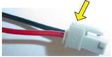
The wires can be removed from the four valves on the manifold by pressing down on the tab at the location of the arrow before pulling straight out. The red and black wires remain connected at the circuit board. Insert the connectors in the same order on the new manifold.
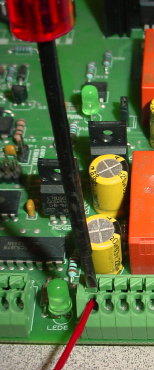
Follow the pink and black wire from the stand alone valve back to the circuit board. The wires are secured by spring terminals. Push down onthe top of the terminal and gently pull the wire out. A finger nail can also be used. Insert the new wire in the same location as the original by pushing down on the tab again.
AIR C- Manifold and the Unloader Valve:
TO REMOVE THE MANIFOLD:
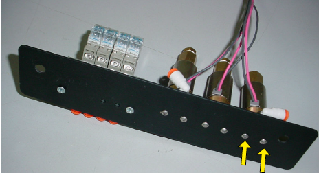
There is a nut and bolt at each end of the manifold. See the arrows. Remove the nuts in order to free the manifold.
TO REMOVE THE STAND ALONE VALVE:
There are two screws that enter the valve from the bottom side of the plate. Use a 1/16" hex wrench to remove the screws.