PARTS:
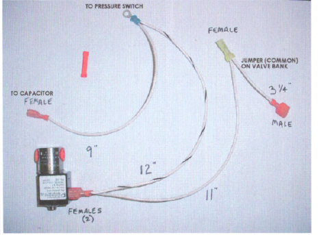
- Jumper wire kit (as in pho to)
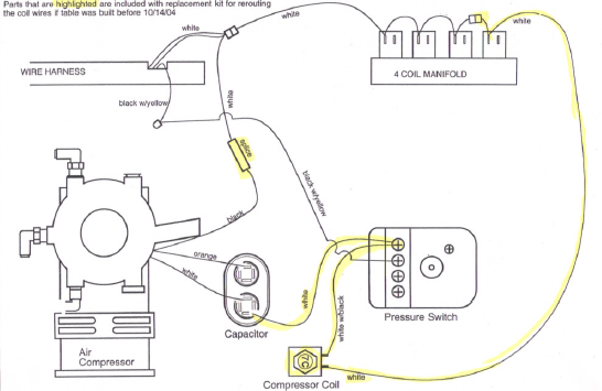
- Wire diagram -WIRE- 178 (part 2) rev. C for newer)
- Find the black wire between the compressor and the pressure switch. Disconnect it at the pressure switch, cut the ring connector off, and strip the end for a crimp connector. (do not put on a connector)
- Find the white wire between the wire harness and the pressure switch. Disconnect it at the pressure switch, cut the ring connector off, and strip the end of the wire for a crimp connector.
- Connect the two wires from steps 1 and 2 above with the straight bull splice that is enclosed.
- Connect the black w/ yellow wire running from the compressor to the terminal on the pressure switch that is indicated in the drawing WIRE 178, part 2, revision C (or newer). Also note that the white wire is now connected lo the last terminal of the pressure switch.
- Use the diagram to route the jumper wires that came in the reroute kit. Disconnect the white wire from the lost coil on the manifold and connect ii to the 3 inch white jumper.