PARTS:
- 89 inches of 12-lead cable soldered to 8-pin Din jack (H7387). The leads at the other end of the cable have female connectors.
- pads for wire ties (9)
- wire ties (12)
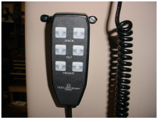
- hand switch
- screws, #6 x 3/8" screws (H96)
- pigtails for all colors IF adding a hand to a foot switch
- 2 qty - footman loops (H1501) with 1/4" long Chicago screws (H7584
- Use the foot pedal to elevate the table to the maximum height. Unplug the table.
- Remove the six screws that secure the plastic enclosure or"skirt" to the steel base. The skirt can be held up with string, tape, or plastic clamps while you work.
-
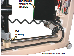
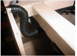
Route the cable below the circuit board and secure it to the inside of the base tube so that it passes along the bottom inside surface of the base so that the B-1 bushing cannot contact it during its travel.
-
Secure the cable to the inside of the cross member at the head end. The cable will go straight up to the side tube of the other scissor. See next photo for detail.
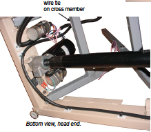
5. Secure the cable to the inside of the scissor tube about eight inches from the end of the scissor tube. Explanation: Step 1 had you elevate the table so that, at Step 5, the maximum amount of cord necessary between the upper and lower wire tie would be determined.
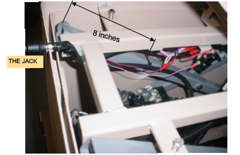
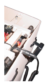
6. Route the end of the cable and jack under the cross member of top frame. Refer to the picture, at right, for the jack's location relative to the top frame.
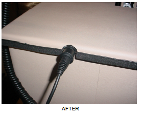
7. Mark the location of the jack on the skirt with a pencil and cut a radius into the top edge for the jack to rest. The top of jack should be flush to top of skirt. The jack is attached to skirt with the #6 screws . Pre drill the two holes 1/8".
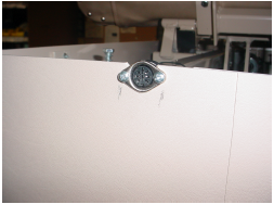
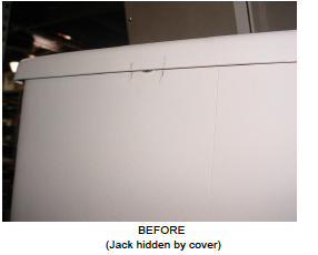
8. Lay the flat cover on top of the skirt and mark to each side of the jack on the black trim with a pencil. Cut the small section of trim and then the plastic around the jack to enable the plug from the switch to be inserted.
9. WIRING AT THE BOARD: Match the color lead to the same terminal and wire color as for foot switch function. Use pigtails of each color to connect the foot and hand switch to the same terminal.
10. The footman loops can be mounted on the skirt where you choose. The photo shows them about three inches down from the top of the skirt and one inch in from where the flat surface begins at the side.