PARTS & PREP:
54" of 4-wire cord, 22ga wire
- cut green wire off both ends
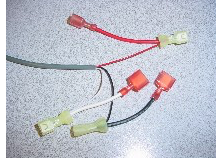
- all male connectors on one end of each color
-3" wire added to each color at other end in a yellow female, male on the 3" wire Corded foot pedal with green and red label, green on right
- cut green wire off
- female connectors on 3 wires Cord clamps with screws (4 each) Heyco cord restraint (1)
Wire ties, 7 1/2" (3) and 6" (3)
male connectors (2)
female connectors (2)


- Use the height pedal to raise the table to the highest position and unplug the table.
- Remove the screws that secure the plastic enclosure to the top frame and pull it away from the frame on the control box side of the table. The KB drive, where the control box wires lead to, is mounted on the scissor. Remove the inner plastic by removing the screws that secure it to the steel base.
- The end of the cord from the new foot pedal can be inserted into the hole of the steel base with about an inch of the black cord inside the base. Use the Heyco cord restraint to secure the cord by wrapping the restraint around the cord and using pliers to squeeze the restraint as it is pushed into the hole.
- Connect the four foot long gray cord to the foot pedal. Secure the cord with a cable clamp, as shown.
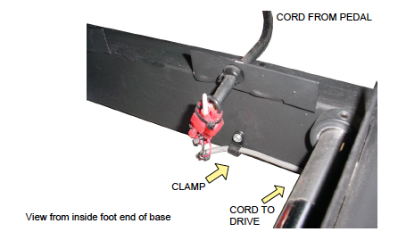
5. Route the gray cord toward the head end following the inside bottom edge of the base. Secure it along the way with 3 more cable clamps, the last one secured before the location where the scissor is pinned to the base. Route the cord up, along the underside of the scissor until it reaches the KB drive. Use wire ties to secure the cord to the scissor.
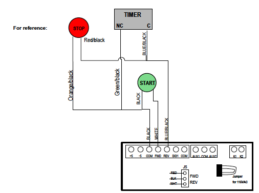
6. The KB drive controls the motor function and is mounted to the scissor. You will need to split the control wires at the bottom end of the drive to provide connections for Start and Stop wires from the additional pedal. To do this, the white control wire will need to be cut and connectors added. The male connector gets crimped on the length of wire still connected to the drive. The female will be crimped to the end of the same color cut from it. The blue with black hash and the black control wires already have connectors that can be separted to add jumpers.
7. Pull the connectors on the black wire apart and connect the black jumper to them. The red jumper will connect to the blue with black hash wires. The white jumper connects to the white that was cut and had connectors added.
8. Test the pedal.
9. Use wire ties to create an orderly appearance of the wires in the KB drive area.