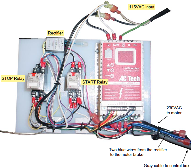
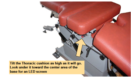
If the pelvic section does not move when the green Start button is pressed for the AFT function it may be because the brake did not release. The next sheet shows the board, located under the thoracic section of the table, that controls communication and power for the AFT function. The component with the "AC Tech" label has a LED window. If the brake does not release at the same time that the motor receives power then the window will show a "CL" indicating that the motor is drawing too much power.
TO DETERMINE THE CAUSE OF BRAKE NOT RELEASING:
- Unplug the table.
- To access the controls shown on Sheet 2, remove the screws securing the plastic enclosure to the top frame. There are two screws at the head and foot,and one on each side.
- Locate the Stop relay and verify that all the wires are connected to the terminals, particularly the white and yellow coming directly from the rectifier.
- Verify that the pink and black wires from the rectifier are securely connected to the two blue wires routed to the motor. The brake is in the motor assembly.
*If wires were secure then the rectifier probably needs to be replaced.
1. Locate the rectifier. Replace it.
AFT Control Board