Instructions for Converting the Air Flex Regular Height to Short Height:
- Replace Actuator Adapter with 10 7/8" length.
- Cut inside skirt to 8 ¼".
Tools and Materials Needed
- 10 7/8 inch long actuator adapter (order from Hill Laboratories)
- Heat gun and 24" (or larger) pipe wrench
- Wire brush, 1/4" alien wrench, 9/16" box wrench
-Table saw
- Non-permanent thread locker adhesive (such as "Loctite")
- Remove the outer skirt, attached with screws to the top frame, so that you can access the inner skirt which is attached to the base with screws.
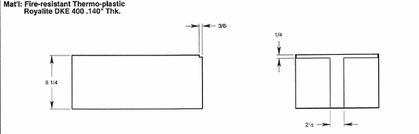
- Remove the inner skirt from the base. Cut the inner skirt down to a height of 8 1/4 inches. This is preferably done on a table saw. The end of the skirt that is open is the foot end. It must have an additional 1/4" removed from it. Refer to drawing # SKT 11-4 on page 2 for detail.
- Turn the table upside down. Make sure the table is lowered to about 1/3 of its available height.
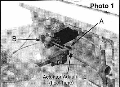
- You must now remove the old actuator Adapter to replace it with a new one. To do this, heat the last inch of he actuator adapter tube where it joins the ball nut to soften the old locktite in the threads (see Photo 1).
5. Using a chain or pipe wrench, unscrew the actuator ball nut from the gray actuator adapter tube (see "A" Photo 1). The table may have to be run to a higher or lower position to release one from the other. Use a wire brush to remove hard ened lock-tite from tube threads once adapter is removed.
NOTE: Right hand threads - standard.
6. Unbolt actuator using a 1/4" alien wrench and the 9/16" box wrench. (see "B" Photo 1)
7. UNPLUG TABLE.
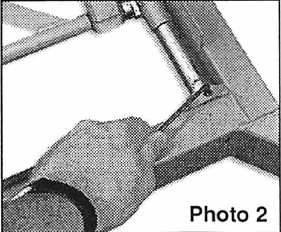
8. Remove all 4 set screws from the lock collars that hold the ends of both glide rods (Photo 2}.
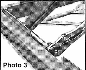
9. With set screws removed, grasp the end of the rods with a vice-grip and turn them repeatedly in a clock wise-counterclockwise fashion until they are loose (Photo 3).
10. Once loose, pull the rods half way out so that the ends come all the way through the bushings (Photo 4).
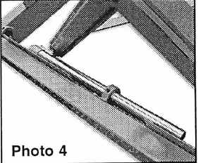
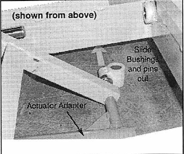
11. Slide the B-1 bushings off of the pins (see photo 4) so that they clear the bottom of the base as shown in the photo. Remove the pins as well so that the actuator Adapter is fully released (shaft collar can remain attached to each).
12. The new actuator adapter can now be threaded onto the actuator and secured with the set screw. The set screw replaces the adhesive that was originally on the large thread ed area of the adapter. This change will make any future service possible without a heat source. A drop of non-perma nent thread locker on the small set screw before it is inserted will ensure that it stays in place.
13. Return the pins (with the collars attached) into the scissors and then into each side of the actuator adapter.
14. Slide the rods back through the new bushings and into the lock collars. Replace the set screws in the lock collars and tighten them. Finally, replace the skirts.