Please see this article for information on accessing and replacing the circuit board.
REPLACE CM132 with CM129 & Move Limit Switches to Motor Side of Circuit
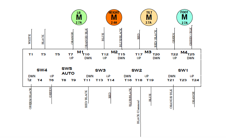
IMPORTANT: the terminals on the CM129 board are in a different order than on the CM132 so follow the color indications given in the drawing provided
PARTS LIST:
1/2” zip loom, 45” long
red wire, 115” long‐2 qty red/blk wire, 115” long 2 qty orange/blk wire, 55” long‐2 qty
connectors ‐ male, female, & ring ‐ 7 qty each wire ties, 6” – 10 qty, 8” ‐ 5 qty
wire diagram – “Replace CM132 with CM129, move limits”
- Disconnect the retractable cord that runs from the board up to the limit switches on the top frame.
- Cut the wire ties securing the zip loom along the inside length of the base and remove just the zip loom. Leave the wires.
- Add the new larger diameter zip loom and both reds and both red/blk wires to the original wires running the length of the base. Do not secure with wire ties yet, just have the wires in the zip loom.
AT FOOT END:
4. At the larger capacitor (for tilt, rated 50uf), remove the original red and red/blk wires and also disconnect the other ends of both from the board. These wires will not be used again.
5. Connect the new red to the same capacitor terminal as the pink. Connect the red/blk to the pink/blk terminal.
6. The other red wire will connect to the new board at the Tilt Up terminal on the new board. The other red/blk wire will connect to the Tilt Down terminal on the new board.
7. Secure the zip loom to the base again once any excess length of wire is pulled toward the head end
AT HEAD END:
8. Add both new orange/blk to the zip loom that is routed up the scissor. Also include both the red and red/blk wires from the other zip loom referred to in step 3.
9. At the smaller of the two capacitors (for lift back, rated 50uf), remove the original orange/blk and connect it to one of the new orange/blk wires. The other orange/blk wire will connect to the original terminal on the capacitor.
TOP FRAME:
10. The red wire connects to the single Tilt limit switch that has a roller. The other red connects to the red wire that was disconnected from the retractable cord in
Step 1. This red routes to the micro switch that serves as a safety switch under the foot end cover.
11. Both red/blk wires connect to same side of the double Tilt/Lift Back micro switch, terminals “C” and “NC”. Both orange/blk wire connect to the other side of the double micro switch, terminals “C” and “NC”.
Limit Switches Moved to Motor Side
Refer to step-by-step instruction sheet for rewiring the table.