Verify that a version of motor firmware is recognized by the PLC.
The picture shows the screen as it appears when the power is first turned on. There is an invisible button below and slightly to the right of the "E" in "FORCE". Press there.
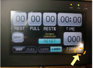
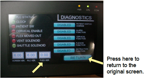
The value should not be "0.00" This would indicate that a cable is broken, motor is not getting power, or the motor does not have firmware. Press "RETURN" at the lower right to return to the original screen.
THE FOLLOWING STEPS WILL HELP DETERMINE THE CAUSE OF "0.00":
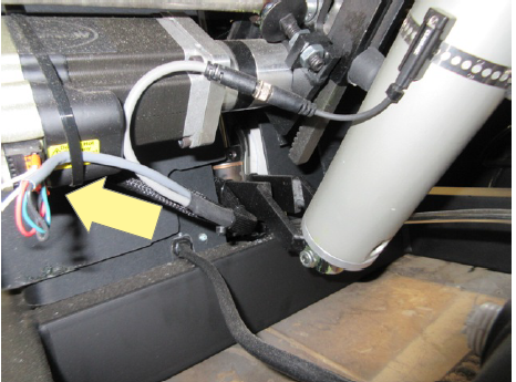
1. Make sure both wire harness connectors are fully inserted into the motor. There is a connector on the side ("A") and one on the bottom edge ("B") as indicated by the two arrows. Try function again.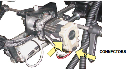
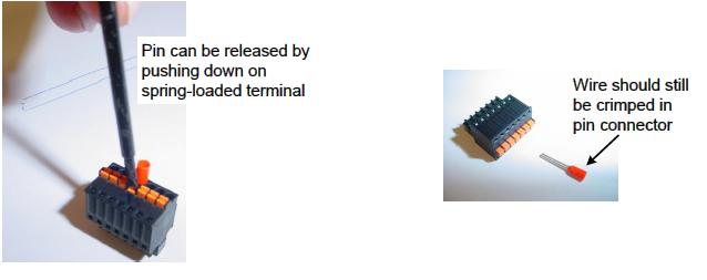
2. Verify that the four colored wires are secure in the the "B" connector at the bottom of the motor. Each wire is crimped in a pin and then inserted in a spring-loaded terminal.
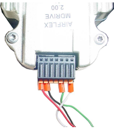
3. Examine the wires where the outer insulation was stripped away to expose the individual color wires to make sure no wire was cut.
4. If everything appears OK on the outside then remove the screws securing the plastic skirt to the base to access inside and examine the same cord at the other end to make sure a wire was not cut when the outer insulation was cut away.
5. Verify that 24 volts DC is being produced by the power supply located on the underside of the scissor. Put the probes on the "-V" AND "+V" terminals.
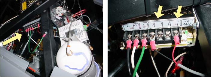
6. Verify that 24 volts DC is being received at the motor through red and black wires. The meter probes can be touched to the red and black wires.