INS - 17
Parts: H219
1. Using the foot pedal, raise the table all the way up.
2. UNPLUG THE TABLE.
3. Using a "Phillips Head" screwdriver, unscrew the six screws around the bottom of the table skirt.
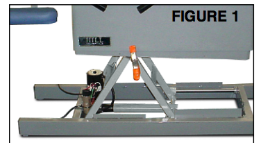
4. Once screws are removed, carefully lift the bottom skirt up so that it "telescopes" inside the top skirt, and while holding it in place, use a clamp like the one in FIGURE 1 to hold it in place.(masking tape can also be used to secure the skirt in its suspended position)
5. Locate the actuator motor as shown in FIGURE 2.
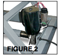
6. Loosen and remove 3/8 bolts on the underside of the motor (see arrows in FIGURE 2).
7. Remove the motor to expose the interior of the casing and the actuator brake. (FIGURE 3)
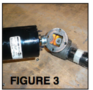
Note: Although the photos show motor removed from table, this is not necessary for procedure.
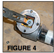
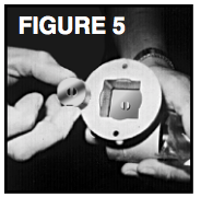
8. Using a needle nose pliers, grasp the actuator brake on both sides and carefully remove (brake should remove easily; see FIGURE 4).
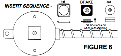
9. Replace the old brake with the new brake and reassemble (see FIGURE 6 for insert sequence). When reassembling the actuator, it is very important that the brake is right side up. You will know that it is if the slotted post in the center is able to protrude up above the metal insert approximately 1/8 of an inch. If the slotted post does not stick up through the insert, then the insert is in upside down. With the insert in properly, the rubber ‘biscuit’ should fit snugly over the slotted post. Once the rubber biscuit is in place, the motor may be reattached.
10. Replace skirt; plug table back in.